Micro Trainer Basic
Start Here
Everything that comes with your Micro Trainer Basic: the free circuit simulator, the video walkthroughs, how to use the board, and support.
Everything that comes with your Micro Trainer Basic: the free circuit simulator, the video walkthroughs, how to use the board, and support.
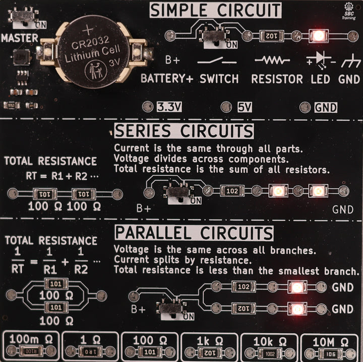
Thank you for your purchase. Your Micro Trainer Basic was assembled and tested by hand before it shipped.
This board teaches the three circuits every other circuit is built out of: simple, series and parallel. Everything a student measures on it is real. The voltages come from the parts on the card, and every junction has a plated test point so a meter lead has somewhere to go.
Everything that comes with it is on this page and all of it is free: a browser-based simulator that mirrors the board, and video walkthroughs as they publish.
If something arrived damaged, skip to warranty and support below. Your email comes to me, not a help desk.
A browser-based simulator that mirrors this board. All three circuits with the current actually moving, the voltage across every part, and a meter you can move from test point to test point to see exactly where the leads go for each measurement.
It also colours the circuit the way a wiring diagram does: what is hot all the time, what is only hot once the switch is made, and what is the ground return.
It runs on any device with a browser. There is also a download button on that page that saves the whole thing as a single file, so it keeps working on a classroom machine with no internet connection.
Simple circuit. One path, one current. The 1 kΩ resistor drops about 3.17 V and the LED about 1.83 V. Add them and you are back at the 5 V source, because every volt that leaves B+ has to be used before it reaches ground. Current is about 3.17 mA.
Series circuit. Same one path, but now two LEDs share it. The resistor drops about 1.40 V and each LED about 1.80 V, and the current falls to about 1.40 mA. The LEDs take the larger share, which is why the resistor gets less than it did on its own. Both LEDs are visibly dimmer than the simple circuit, which is what less current looks like.
Parallel circuit. Two branches, each with its own resistor and LED. Both see the full 5 V, both draw about 3.17 mA, and the supply provides about 6.34 mA in total. Both LEDs are as bright as the simple circuit, and the branch currents add up at the split.
Total resistance. The two 100 Ω test pairs on the card are the formulas made measurable. In series they add to 200 Ω. In parallel they come to 50 Ω, lower than either resistor on its own.
Each circuit gets a short video: the simulator first so the idea is clear, then the same measurement taken on the real board so the numbers can be compared side by side.
Videos are going up one at a time. Bookmark this page rather than the individual videos, because as more publish they land here.
Two switches to get a circuit running. MASTER powers the whole card. Each circuit then has its own switch. If nothing lights up, check MASTER first.
Battery. One CR2032. Switch MASTER off when you are done and a cell lasts a long time.
Every junction is a test point. The plated pads either side of each part are there so a student can measure across one component at a time instead of guessing.
Measuring current without cutting anything. There is no track to cut on this board, so use the switch as the break. Turn the circuit switch off, put one lead on the test point before it and one on the test point after it, and the meter becomes the only path round the loop. The LED lights through the meter and it reads the running current.
Resistance is measured dead. The test pairs and the reference resistors along the bottom edge sit on their own pads with nothing else wired to them, so there is nothing to switch off first. On a vehicle that is never true: power off and the part isolated, or you are measuring the rest of the car as well.
Check your meter against known values. The six resistors along the bottom run from 100 mΩ to 10 MΩ. Below about 1 Ω your leads are a real part of the reading, which is worth showing a student once.
Every board is tested before it ships. If one arrived damaged or fails in normal classroom use, email me and I will make it right.
Include your order number and a photo of the board if you can, which usually gets it sorted in one reply.
Email: scott@sbctrainingllc.com
Thank you for supporting a small shop. This board exists because series and parallel get taught on a whiteboard and then never measured, and students end up able to recite the formulas without recognising either circuit in front of them.
I build trainers and curriculum for other systems too, including CAN bus, lead acid batteries and relays. If your program needs something that does not exist yet, tell me what you are trying to teach and I will tell you honestly whether I can build it.
Questions about any of it, or a warranty issue?